
Get Support
+8801977426642
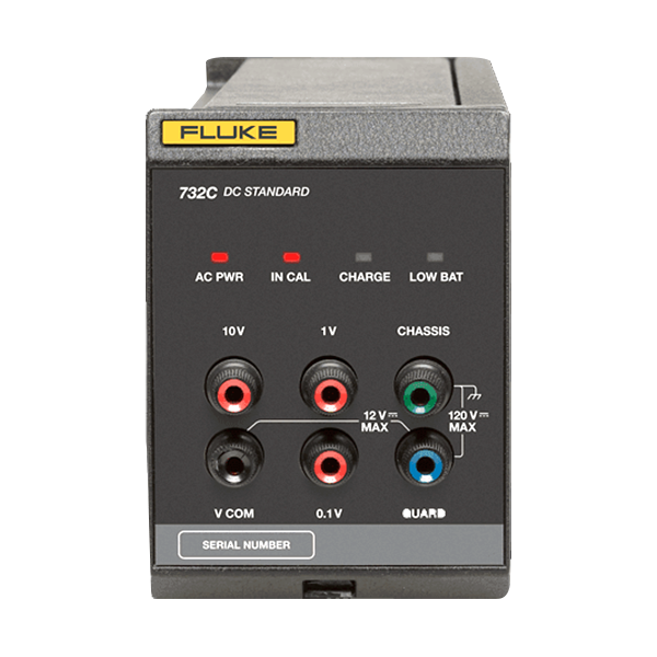
Model: 732C and 734C DC Voltage Reference Standards
The simple way to maintain and disseminate the volt. The Fluke Calibration 732C DC Voltage Reference Standard is a RoHS-compliant direct voltage reference used to maintain the voltage in primary and secondary standards laboratories.
Individual 732C voltage standards provide 10 V, 1 V, and 0.1 V outputs and may be transported easily to remote locations while the dc reference is maintained in the laboratory.
The Fluke 734C DC Voltage Reference Standard consists of four electrically and mechanically independent 732C DC Reference Standards and a rack-width enclosure. Two model families, Base and Select, differ in that the Select models are two times more stable than the Base models.
Key Features: Fluke 732C and 734C DC Voltage Reference Standards
- The 734C is the only standard of its type offering complete mechanical and electrical independence of each of its four standards.
- Each 732C Standard is designed for portability. Each is small, light, rugged and has long operating battery life.
- The 732C is based on the proven technology of the Fluke Calibration 732A and 732B. The 732A was the first standards lab quality electronic reference to gain wide acceptance as a replacement for saturated standard cells. Originally designed for internal transfers of Fluke’s corporate volt to the production floor, thousands are now in service worldwide in a variety of applications—from maintaining an institutional reference to transferring values from national labs or privately-operated 10 V Josephson Arrays.
Specifications: 732C and 734C DC Voltage Reference Standards
Line voltage is accepted as shown in Table 1. AC line current at 120V AC is typically 0.13A. Table 1. Mains
| 732C Line Voltage Setting | Line Voltage Accepted | Frequency Accepted |
|---|---|---|
| 100 V | 90 V to 110 V | 50 Hz/60 Hz |
| 120 V | 108 V to 132 V | 50 Hz/60 Hz |
| 220 V | 198 V to 242 V | 50 Hz/60 Hz |
| 240 V | 216 V to 264 V | 50 Hz/60 Hz |
| Battery | Battery Operation | At full charge, the internal battery operates the Product for a minimum of 72hours at 23±5 °C, with 0 mA to 0.1 mA total current drain at the outputs. |
| Charging Time | <36 hours with self-contained automatic battery charger | |
| External DC Input | Rear-panel input for external 12 V dc to 15 V dc powers the Product indefinitely. The dc source must be rated ≥300 mA. | |
| Isolation | Resistance from any of the Product binding posts to earth (chassis) ground or to ac line power is >10 000 MΩ shunted by <1000 pF. | |
| Guard and Ground Terminals | Chassis ground connections are provided on both the front and rear panels. Access to the internal guard is provided by a front-panel binding post. | |
| Output Protection | All outputs can be shorted indefinitely without damage to the Product. The 10 V output can withstand voltages from other sources as follows:
|
|
| Environmental | |
|---|---|
| Specified Operation | Temperature Range: 15 °C to 35 °C |
| Relative Humidity: 0% to 90% to 28 °C, to 80% to 35 °C, and to 50% to 50 °C, Noncondensing | |
| Altitude: 0 m to 1830 m (0 ft to 6000 ft) | |
| Non-specified Operation | Temperature Range: 0 °C to 50 °C |
| Relative Humidity: 0% to 90% Noncondensing | |
| Altitude: 0 m to 3050 m (0ft to 10 000ft) | |
| Storage (Battery Removed) | Temperature Range: -40 °C to 50 °C |
| Relative Humidity: Noncondensing | |
| Altitude: 0m to 12 200 m (0 ft to 40 000 ft) | |
| Electromagnetic Compatibility | |
|---|---|
|
(EMC) The Product operates in Standards Laboratory environments where the radio frequency (RF) environment is highly controlled. |
|
| International |
IEC 61326-2-1; CISPR 11: Group 1, Class A Controlled Electromagnetic Environment Group 1 equipment has intentionally generated and/or use conductively coupled radio-frequency energy which is necessary for the internal functioning of the equipment itself. Class A equipment is equipment suitable for use in all establishments other than domestic and those directly connected to a low voltage power supply network which supplies buildings used for domestic purposes. Emissions which exceed the levels required by CISPR 11 can occur when the equipment is connected to a test object. The equipment may not meet the immunity requirements of 61326-1 when test leads and/or test probes are connected. |
| USA (FCC) | 47 CFR 15 subpart B, this product is considered an exempt device per clause 15.103 |
| Korea (KCC) |
Class A Equipment (Industrial Broadcasting & Communication Equipment) This product meets requirements for industrial (Class A) electromagnetic wave equipment and the seller or user should take notice of it. This equipment is intended for use in business environments and not to be used in homes. |
| Safety | |
|---|---|
| Safety | IEC 61010-1, Installation Category II, Pollution degree 2 |
| Ingress Protection | IEC 60529: IP20 |
| Mechanical Specifications | ||
|---|---|---|
| 734C Dimensions | 732C and 732C-7001 Dimensions | |
| Height | 17.8 cm (7.0 in) | 13.4 cm (5.28 in) |
| Width | 43.2 cm (17.0 in) | 9.8 cm (3.85 in) |
| Depth | 50.3 cm (19.8 in) including handles | 40.6 cm (16.0 in) |
| Weight | 30.4 kg (67 lb) | 5.91 kg (13 lb) |
Performance Specifications
Output Voltages
10 V, 1 V, and 0.1 V are provided at separate binding posts referenced to the VCOM binding post.
Stability
Stability for the 732C outputs at Tcal ±1 °C and IN CAL indicator on is specified in Table 2.
Table 2. Standard Stability
| Output Voltage | Stability (± µV/V) | ||
| 30 Days | 90 Days | 1 Year | |
| 10 V | 0.3 | 0.8 | 2.0 |
| 1 V | 0.6 | 1.2 | 3.0 |
| 0.1 V | 1.2 | 2.9 | 9.8 |
Table 3. Select Stability
| Output Voltage | Stability (± µV/V) | ||
|---|---|---|---|
| 30 Days | 90 Days | 1 Year | |
| 10 V | 0.3 | 0.8 | 1.0 |
| 1 V | 0.6 | 1.2 | 2.5 |
| 0.1 V | 1.2 | 2.9 | 8.0 |
Noise at the Output Terminals
Output noise is specified for both day-to-day observations and for short-term observations, at k=1.
Table 4. Noise at the Output Terminals
| Output Voltage | S1 (±µV/V) |
|---|


